
Tseetech releases TE03, a 200 W mid-power wireless charging module
- # E-mobility
- # Robots
As phone wireless charging has become common, people have come to value how convenient it is. Beyond low-power consumer electronics, wireless charging has a broad set of mid-power applications — e-bikes, inspection AGVs and mobile robots in particular are large potential markets. For a long time, though, technical hurdles such as charging efficiency and foreign object detection kept wireless charging rare in these markets.
Tseetech focuses on the research, development and industrialization of wireless charging, with solutions ranging from a few watts upwards. Starting with our 50 mm through-surface phone charger in 2020, we have kept exploring different power ranges for different markets. Tseetech has now released TE03, a wireless charging module for the 200 W mid-power market. This article answers the technical questions people ask most about it.
Specifications
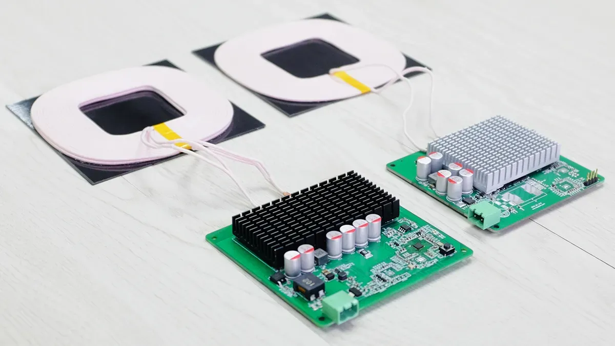
The 200 W module consists of a transmitter (Tx, left) and a receiver (Rx, right). Both use green PCBs, each with its own heatsinks.
| Item | Value |
|---|---|
| Power input | 48 V / 6 A |
| Power output | 54.2 V, 2 A / 3 A / 4 A |
| Connectors | Customizable |
| Charging efficiency | 91% at 25 mm |
| Protection | FOD, OCP, OVP, OTP |
| Standby power | ≤ 0.5 W |
| Charging distance | 15–35 mm |
| Transmitter size | Control board 100 × 100 × 18 mm; coil module 120 × 120 × 8 mm (L × W × H) |
| Receiver size | Control board 90 × 90 × 18 mm; coil module 120 × 120 × 5.5 mm (L × W × H) |
The transmitter PCB measures 100 × 100 × 18 mm with a 120 × 120 × 8 mm coil; the receiver PCB measures 90 × 90 × 18 mm with a 120 × 120 × 5.5 mm coil. The transmitter takes a 48 V / 6 A input; the receiver has a fixed 54.2 V output with a 2 A, 3 A or 4 A current setting, for up to about 200 W.
Both boards have customizable power connectors and support FOD, OCP, OVP and OTP protection. The charging distance is 15–35 mm, with an efficiency of 91% at 25 mm.
Performance tests
- Efficiency
We first tested the module’s efficiency at an ambient temperature of 24.8 °C, powered by an ITECH IT6722A DC supply with an ITECH IT8512A electronic load.
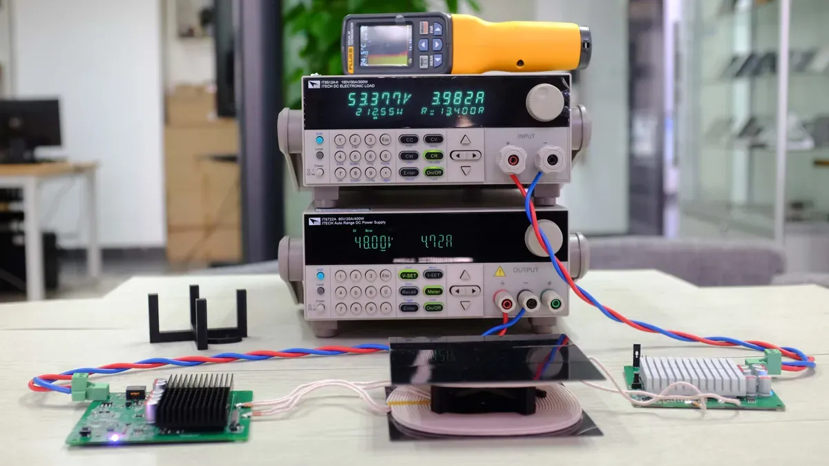
The photo shows the module with a 20 mm gap between the transmitter and receiver coils and a 4 A output. The DC supply read 48 V and 4.72 A; the electronic load read 53.377 V and 3.982 A, which works out to an efficiency of about 93%.
| Gap | Output setting | Input current (A) | Input power (W) | Output voltage (V) | Output current (A) | Output power (W) | Efficiency |
|---|---|---|---|---|---|---|---|
| 15 mm | 2 A | 2.39 | 114.72 | 53.80 | 1.99 | 107.06 | 93.32% |
| 3 A | 3.59 | 172.32 | 53.70 | 2.98 | 160.03 | 92.87% | |
| 4 A | 4.80 | 230.40 | 53.80 | 3.96 | 213.05 | 92.47% | |
| 20 mm | 2 A | 2.40 | 115.20 | 53.80 | 1.99 | 107.06 | 92.94% |
| 3 A | 3.62 | 173.76 | 53.80 | 2.99 | 160.86 | 92.58% | |
| 4 A | 4.82 | 231.36 | 53.60 | 3.97 | 212.79 | 91.97% | |
| 25 mm | 2 A | 2.43 | 116.64 | 54.00 | 2.00 | 108.00 | 92.59% |
| 3 A | 3.63 | 174.24 | 53.80 | 2.99 | 160.86 | 92.32% | |
| 4 A | 4.86 | 233.28 | 53.60 | 3.97 | 212.79 | 91.22% | |
| 30 mm | 2 A | 2.46 | 118.08 | 54.00 | 2.00 | 108.00 | 91.46% |
| 3 A | 3.67 | 176.16 | 53.80 | 2.99 | 160.86 | 91.32% | |
| 4 A | 4.89 | 234.72 | 53.70 | 3.98 | 213.73 | 91.06% | |
| 35 mm | 2 A | 2.49 | 119.52 | 54.00 | 2.00 | 108.00 | 90.36% |
| 3 A | 3.75 | 180.00 | 54.00 | 3.00 | 162.00 | 90.00% | |
| 4 A | 4.93 | 236.64 | 53.60 | 3.97 | 212.79 | 89.92% |
Input voltage 48.00 V in all cases.
These are the module’s efficiency figures at different gaps and output currents. At 15–20 mm the system efficiency is around 92%; at 25–30 mm it stays above 91%; even at 35 mm it is about 90%.
Transfer efficiency is one of the key measures of a wireless charging system; in these tests it is about 90% or higher throughout.
2. Offset
We also tested different gaps, offsets and output currents to see how coil misalignment affects efficiency.
| Gap | X/Y offset | Input current (A) | Input power (W) | Output voltage (V) | Output current (A) | Output power (W) | Efficiency |
|---|---|---|---|---|---|---|---|
| 15 mm | 0 | 4.80 | 230.40 | 53.80 | 3.96 | 213.05 | 92.47% |
| +10 mm | 4.85 | 232.80 | 53.80 | 3.98 | 214.12 | 91.98% | |
| +20 mm | 4.87 | 233.76 | 53.60 | 3.97 | 212.79 | 91.03% | |
| 20 mm | 0 | 4.82 | 231.36 | 53.60 | 3.97 | 212.79 | 91.97% |
| +10 mm | 4.84 | 232.32 | 53.60 | 3.97 | 212.79 | 91.59% | |
| +20 mm | 4.89 | 234.72 | 53.60 | 3.97 | 212.79 | 90.66% | |
| 25 mm | 0 | 4.86 | 233.28 | 53.60 | 3.97 | 212.79 | 91.22% |
| +10 mm | 4.91 | 235.68 | 53.70 | 3.97 | 213.19 | 90.46% | |
| +20 mm | 4.93 | 236.64 | 53.70 | 3.97 | 213.19 | 90.09% | |
| 30 mm | 0 | 4.89 | 234.72 | 53.70 | 3.98 | 213.73 | 91.06% |
| +10 mm | 4.89 | 234.72 | 53.60 | 3.97 | 212.79 | 90.66% | |
| +20 mm | 4.98 | 239.04 | 53.70 | 3.98 | 213.73 | 89.41% | |
| 35 mm | 0 | 4.93 | 236.64 | 53.60 | 3.97 | 212.79 | 89.92% |
| +10 mm | 4.95 | 237.60 | 53.70 | 3.97 | 213.19 | 89.73% | |
| +20 mm | 5.01 | 240.48 | 53.70 | 3.97 | 213.19 | 88.65% |
Input voltage 48 V, 4 A output setting; offset applied in both X and Y.
These are the results at 15–35 mm gaps with 10 mm and 20 mm offsets. Up to a 25 mm gap and a 20 mm offset, efficiency stays above 90%; at 30 mm with a 20 mm offset it is about 89.4%. Charging does not depend on precise alignment.
- Foreign object detection (FOD)
Metal in the charging area is heated by eddy currents and can damage equipment or even start a fire. Foreign object detection keeps metal from being heated in the field. We tested FOD both at power-up (standby) and during operation.
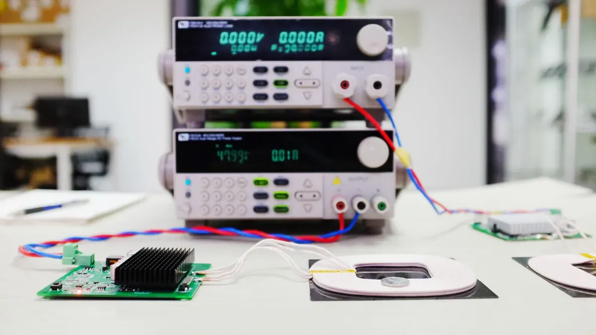
First we placed a 1-jiao coin on the transmitter coil. The DC supply showed no output current, so the transmitter detects metal objects at power-up and avoids heating metal in practical use.
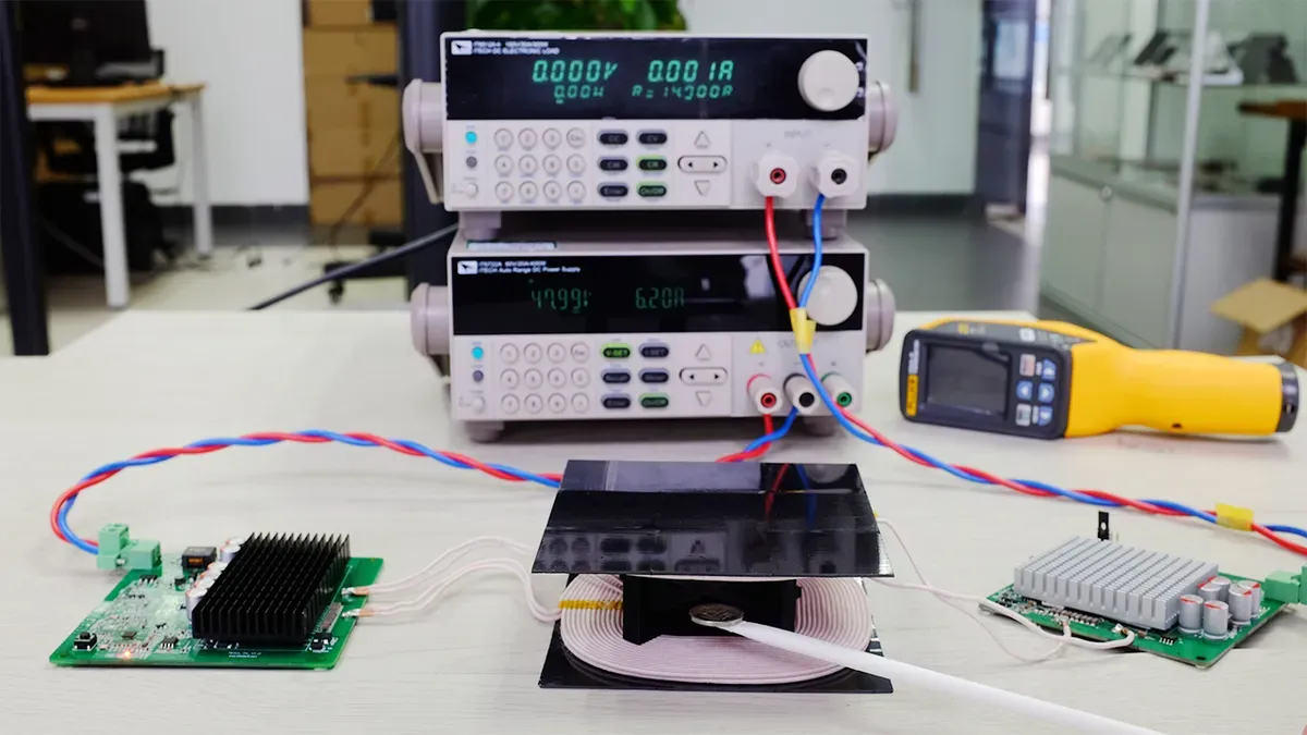
We also tested FOD during operation. With a 35 mm gap between the coils, the DC supply and electronic load connected and the system charging normally, we placed a 1-jiao coin between the two coils. The system stopped transferring power, showing that it had detected the metal object and triggered foreign object detection.
| Charging distance | Standby: 1 jiao | Standby: 5 jiao | Standby: 1 yuan | Operating: 1 jiao | Operating: 5 jiao | Operating: 1 yuan |
|---|---|---|---|---|---|---|
| 15 mm | ✓ | ✓ | ✓ | ✓ | ✓ | ✓ |
| 20 mm | ✓ | ✓ | ✓ | ✓ | ✓ | ✓ |
| 25 mm | ✓ | ✓ | ✓ | ✓ | ✓ | ✓ |
| 30 mm | ✓ | ✓ | ✓ | ✓ | ✓ | ✓ |
| 35 mm | ✓ | ✓ | ✓ | ✓ | ✓ | ✓ |
We also tested FOD at power-up and during operation at gaps of 15, 20, 25, 30 and 35 mm. In every one of these test cases the system identified the coin and stopped charging.
FOD is one of the protection mechanisms of a wireless charging system. Tseetech’s R&D team refined the FOD algorithm for this solution over several iterations.
- Temperature rise
For the temperature-rise test, the ambient temperature was 24.9 °C and the charging distance 20 mm. After one hour at 200 W output, we recorded temperatures with a FLUKE VT04A thermal imager.
The transmitter (Tx) reached about 67.9 °C at its hottest point, the coil about 42 °C and the receiver (Rx) about 58.3 °C.
We then repeated the one-hour test at 200 W output with a 35 mm charging distance at the same 24.9 °C ambient temperature and checked the transmitter and receiver again.