Rectifier circuits for wireless power receivers: types and trade-offs
- # Circuit design
A rectifier converts AC into DC. It is one of the basic circuits of power electronics and is used throughout electronic devices and power systems; in a wireless power receiver, it turns the high-frequency AC picked up by the receiving coil into DC for the load. The common rectifier circuits fall into the following types.
1. Diode half-wave rectifier
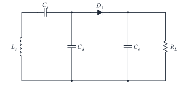
The diode half-wave rectifier is the most basic form of rectifier: a single diode does the rectification, as shown in Figure 1. It relies on the diode conducting in one direction only. During the positive half-cycle of the AC voltage, the diode is forward-biased and current flows to the output; during the negative half-cycle, it is reverse-biased, blocks the current, and the output voltage is zero. Only half of each AC cycle is used, so the output is half of the original waveform. Without filtering, the average output voltage is about 1/π (roughly 0.32) of the AC peak; with a filter capacitor it approaches the peak, depending on the load. The circuit is very low-cost, but its output ripple is large, so it suits applications with modest accuracy requirements, tight cost limits and low load current.
2. Diode full-bridge rectifier
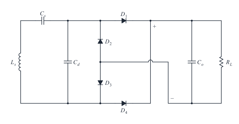
The diode full-bridge rectifier uses four diodes, D1 to D4, connected in a bridge, as shown in Figure 2. The receiving coil Ls picks up high-frequency AC. During the positive half-cycle, D1 and D3 conduct while D2 and D4 are reverse-biased and off; during the negative half-cycle, D2 and D4 conduct while D1 and D3 are off. With the two diode pairs conducting alternately, the circuit rectifies the whole input waveform and delivers a DC output with little ripple.
Because it uses both half-cycles, the full-bridge rectifier is efficient, gives a steadier output with less ripple, and is relatively simple to build and maintain. However, each conducting diode has a forward voltage drop, and the resulting loss grows with current, so this circuit is less suited to high output currents.
3. Semi-controlled rectifier
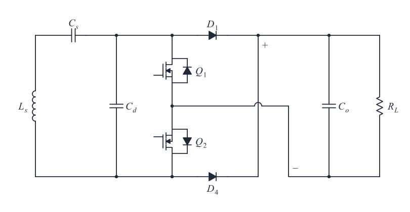
The semi-controlled (half-controlled) rectifier was developed to reduce the conduction losses caused by diode voltage drops in the full-bridge rectifier. Its topology is shown in Figure 3: diodes D2 and D3 of the full-bridge rectifier (Figure 2) are replaced by controllable switches, which are turned on and off by control signals, while the remaining diodes conduct and block naturally. It works much like the diode full bridge, with slightly higher efficiency. In addition, by adjusting the gate signals that drive Q1 and Q2, the output DC voltage can be varied, which adds some flexibility. Semi-controlled rectifiers are usually used at low to medium power; they are generally not the best choice for high-power systems or for systems that need high precision and high efficiency.
4. Full-bridge synchronous rectifier
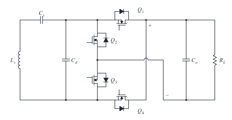
The full-bridge synchronous rectifier is a high-efficiency rectifier suited to high frequencies. It uses controllable switches instead of diodes. As shown in Figure 4, during the positive half-cycle of the AC voltage, switches Q1 and Q3 are turned on in sequence while Q2 and Q4 stay off, and current flows from the input to the output through Q1 and Q3. During the negative half-cycle, Q2 and Q4 are turned on in turn while Q1 and Q3 are off, and current again flows to the output in the same direction, this time through Q2 and Q4. The switches thus steer the current so that the output always sees one polarity.
Synchronous rectifiers use MOSFETs (metal-oxide-semiconductor field-effect transistors) or similar switches, whose on-resistance is much lower than the forward drop of a Schottky or ordinary PN-junction diode. The lower on-state voltage drop significantly reduces conduction losses and raises the efficiency of the whole system. MOSFETs also switch faster than diodes recover, so full-bridge synchronous rectifiers can run at higher frequencies, allowing a smaller, lighter filter and a more compact design.