
Wireless power inverters: full-bridge, half-bridge or push-pull?
- # Circuit design
The inverter converts DC into high-frequency AC to drive the transmitter coil, and it is a key power stage of any wireless charging system. By controlling the switching frequency it keeps the system close to its designed resonant frequency; only near resonance can the system deliver maximum power while keeping losses and electromagnetic interference low. Four inverter types are common in wireless charging: full-bridge, half-bridge, push-pull and class E. Full-bridge and half-bridge inverters are also known as class-D inverters.
1. Full-bridge inverter
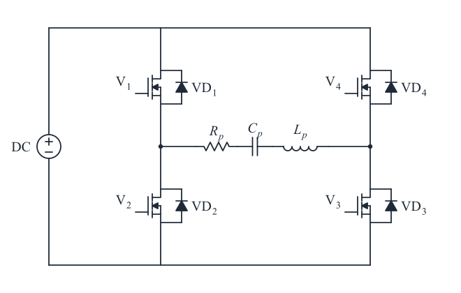
A full bridge uses four switches and can be seen as two half bridges working in opposition. When Q1 and Q4 conduct, current flows through the load in one direction; when Q2 and Q3 conduct, it reverses. The load sees a square wave with an amplitude close to the DC supply voltage.
- Advantages: the output amplitude equals the DC voltage, twice that of a half bridge, so it can deliver more power; it feeds the resonant network during the whole switching period; output power can be adjusted over a wide range through switching frequency and duty cycle.
- Disadvantages: more switches, and the gate drive needs precise timing so that the upper and lower switches of a leg never conduct at the same time.
Medium- and high-power wireless charging systems usually use a full-bridge inverter.
2. Half-bridge inverter
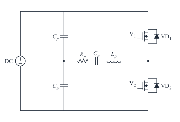
A half bridge has two switches that conduct alternately, each for half of the period.
- Advantages: only two switches, low hardware cost and relatively simple drive circuitry.
- Disadvantages: the AC output amplitude is only half the DC input voltage, so the same power requires more current and higher current capability from the devices. Half bridges are therefore mainly used at lower power levels.
3. Push-pull inverter
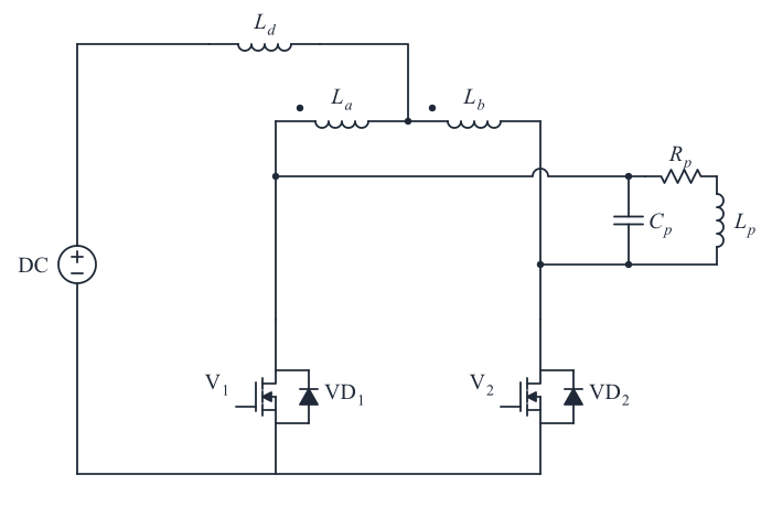
A push-pull inverter uses two switches and a center-tapped transformer. The switches conduct alternately and energy is coupled to the secondary through the transformer.
- Advantages: only two switches and simple timing, with no complementary bridge-leg logic.
- Disadvantages: each switch sees about twice the input voltage when it turns off, which raises voltage-rating and thermal requirements; ringing between the transformer’s leakage inductance and stray capacitance causes significant switching losses and EMI; the transformer core must resist saturation. Push-pull inverters are therefore used mainly with low input voltages and at low power.
4. Class-E inverter
A class-E inverter consists of a single switch, an LC resonant circuit and a load network. The switch turns on and off at zero voltage or zero current (soft switching), so switching losses are small, efficiency can be very high, and the smooth waveforms produce little high-frequency noise.
- Disadvantages: the resonant components must be matched precisely to the switching frequency, which makes tuning difficult, and efficiency is sensitive to load changes and drops noticeably away from the design load. Class-E inverters are mostly used at low to medium power with fairly stable loads.
How to choose
| Topology | Switches | Output amplitude | Typical use |
|---|---|---|---|
| Full-bridge | 4 | about the DC voltage | medium and high power, wide power adjustment |
| Half-bridge | 2 | about half the DC voltage | lower power, cost-sensitive designs |
| Push-pull | 2 plus a center-tapped transformer | set by the transformer | low input voltage, low power |
| Class E | 1 | depends on the resonant design | high frequency, low to medium power, stable load |