
Coupling factor k: how coil gap and offset affect power transfer
- # Coils & magnetics
Only part of the magnetic flux produced by the transmitter coil (Tx) passes through the receiver coil (Rx) and takes part in power transfer; the rest leaks into the surroundings. The larger the share that reaches the receiver, the more tightly the coils are coupled. The parameter that describes this is the coupling factor, k.
What k means
k lies between 0 and 1:
- k = 1 is perfect coupling — all flux from Tx passes through Rx;
- k = 0 means the coils are not coupled at all.
Phone chargers keep the coils very close, so k is usually high. In robots and drones the gap is larger and the docking position varies, so k is often only a few tenths — a loosely coupled system. Tseetech’s solutions are designed for exactly this kind of loose coupling.
How gap and offset change k
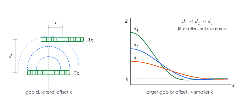
k depends on the distance between the coils, their relative size, their shape and the angle between them. For two parallel planar coils:
- when the coils are aligned, a larger gap d gives a smaller k;
- at a fixed gap, a larger lateral offset x also gives a smaller k;
- at large offsets k can approach zero or even dip slightly below it, meaning the receiver picks up flux “from behind”.
Definition and measurement
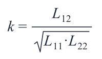
The coupling factor is defined from the mutual inductance and the two self-inductances:
It follows from the general equations for coupled inductors:
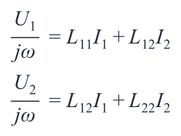
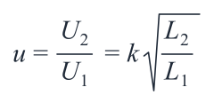
where U₁ and U₂ are the coil voltages, I₁ and I₂ the coil currents, L₁₁ and L₂₂ (L₁ and L₂) the self-inductances, L₁₂ the mutual inductance and ω = 2πf the angular frequency.
On an existing system, k can be estimated by driving one coil and measuring the open-circuit voltage on the other:
What it means when choosing a solution
The lower k is, the more coil current is needed for the same output power — so losses rise and control gets harder. When selecting a solution, evaluate efficiency and temperature rise at your real installation gap and maximum offset, not just the aligned, nominal figure. Early in a project, Tseetech sizes the coils and sets the allowed offset range from the device’s docking accuracy and available space.
Further reading: WPC knowledge base — Coupling factor