Choosing coil wire and ferrite shielding for wireless charging
- # Coils & magnetics
Note: Translated from the Chinese original.
With direct current, the current density is uniform across the wire’s cross-section. With alternating current, the skin effect sets in: the alternating field induces eddy currents inside the conductor, so the current density concentrates near the surface and falls off toward the center. The effective conducting area shrinks, more so at higher frequencies. From R = ρL/S, the skin effect therefore raises the wire’s resistance, increasing losses in the wire and its temperature rise.
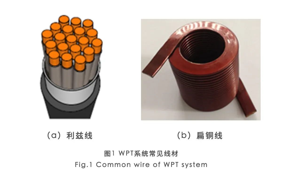
To reduce the skin effect, wireless charging coils commonly use one of two conductors, Litz wire or flat copper, as shown in Figure 1. Figure 1(a) is Litz wire: many insulated copper strands twisted together. Each strand has a small cross-section, which increases the total effective conducting area. Figure 1(b) is flat copper, which counters the skin effect by increasing the conductor’s surface area relative to its interior; the most common forms are stamped flat copper and printed circuit boards (PCB). Both reduce, to some extent, the loss of effective conducting area caused by the skin effect. Comparing the two, though, flat copper must be quite wide to carry high currents, which makes the whole coil much larger. Where product size is constrained, Litz wire is therefore the usual choice: compared with flat copper it has lower high-frequency losses and is less demanding to manufacture.
In a wireless charging system, ferrite sheets are an auxiliary material for both coils. They gather the magnetic field lines so energy is not dispersed, which would hurt system efficiency, and they prevent stray flux that could interfere with other equipment. A ferrite sheet under the transmitter coil guides the flux through its own low-reluctance path, so the field below the coil is much weaker and disturbs the circuitry less, while the field above the coil becomes stronger. A ferrite sheet above the receiver coil stops the field from heating metal parts around the receiver, and also concentrates flux into the receiver coil, raising the coupling factor between the coils and so improving transfer efficiency.
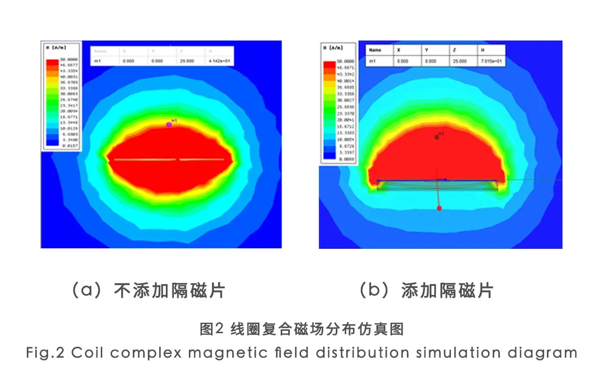
The most widely used ferrite material today is PC95, introduced by TDK in 2003. It offers a wide temperature range, low losses and relatively high permeability, and is used in many kinds of electronic products. Figure 2 shows simulated field distributions for a coil without and with a ferrite sheet. With the ferrite added below the coil, the field beneath it is clearly weaker and the field above the coil is clearly stronger.